

Design & Planning Intelligence
Spatially informed solar access analysis for architectural design, planning assessment and clearer communication of how surrounding context affects sunlight.
For architects, building designers, planners and development teams assessing orientation, obstruction and seasonal solar access.
Send Your Project DocumentsIn Brief
A Sun Eye Diagram is a three-dimensional solar analysis view showing the position of the sun in relation to a building, site and surrounding development at a selected date and time. It helps illustrate which façades, windows, apartments, courtyards and outdoor spaces may receive direct sunlight, as well as which built elements may obstruct it.
The analysis combines project geometry, geographic orientation and location-specific sun positioning. Where suitable contextual information is available, Urbanfinity Spatial Data can place the proposal within a georeferenced representation of surrounding buildings, terrain and urban form. This provides a clearer understanding of solar access than a generic sun-path graphic viewed without project context.
Sun Eye Diagrams can support architectural design, building-massing studies, façade and shading decisions, planning communication and solar access assessment. They differ from Shadow Diagrams: Sun Eye analysis explains the spatial relationship between sunlight and a building, while shadow analysis primarily shows where a building casts shadow at nominated dates and times.
The relationship between sunlight, building form, façades, openings, outdoor areas and surrounding development.
Architectural geometry, site orientation, location-specific solar data and available Urbanfinity spatial context.
Sun Eye analysis explains solar reach and exposure, while Shadow Diagrams show where a building’s shadow falls.
Knowledge Navigation
Use this guide to explore the principles, project applications and spatial information behind Sun Eye Diagrams and three-dimensional solar access analysis.
Foundation
Learn how three-dimensional solar views represent sun position, direct solar access and surrounding obstruction.
Solar Movement
Understand how solar altitude, direction, time of day and season change the way sunlight reaches a site.
Spatial Context
See how georeferenced buildings, terrain and urban form can strengthen project-specific solar analysis.
Design Response
Explore how solar analysis can inform massing, setbacks, openings, eaves and façade design.
Comparison
Understand the different questions answered by solar access views and conventional shadow analysis.
Project Use
Review common residential, commercial and planning uses, required information and project outputs.
Architectural & Environmental Response
Understand how sunlight reaches a proposed building, its façades, outdoor spaces and surrounding context through location-specific three-dimensional solar analysis.
Certified Energy combines architectural project information, geolocated sun-path analysis and Urbanfinity spatial context data to illustrate how the sun interacts with a development across different times of day and seasons. The resulting diagrams can support design development, solar access assessment, planning communication and the review of building orientation, massing and shading response.
Understanding the Method
Sun Eye Diagrams are three-dimensional solar access views that represent the position of the sun in relation to a building, site and surrounding context at a selected date and time. They help show which parts of a proposal are exposed to direct sunlight, which elements create obstruction and how solar access changes as the sun moves across the sky.
Unlike a generic sun path chart, a project-specific Sun Eye Diagram is tied to the geographic location, orientation and geometry of the development being assessed. The analysis can include proposed buildings, existing surrounding development, terrain and other contextual features that may influence the path of direct sunlight.
This makes the diagrams useful for more than simply illustrating where the sun is located. They can provide a clear visual explanation of the relationship between solar position, building massing, façades, windows, balconies, courtyards and shared outdoor spaces. For complex sites, this three-dimensional relationship may be easier to interpret than conventional plans and elevations viewed independently.
The solar position is calculated for the project location rather than applied as a generic diagram.
Views can be prepared for nominated dates and times to investigate daily and seasonal solar conditions.
Surrounding built form and terrain can be included to show how the wider site context affects solar access.
Core distinction
A Sun Eye Diagram explains how the sun relates to the building. It is not simply a drawing of the shadow cast by the building.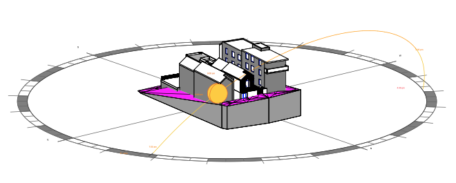
Solar Design Intelligence
Sun Eye Diagrams help project teams understand how sunlight approaches and reaches a building, façade or external space throughout the year. They translate complex solar geometry into a clear three dimensional visual reference that can inform early design decisions before orientation, massing and façade responses become difficult to change.
01
See how seasonal sun positions relate to the form, orientation and surrounding context of the project. This makes solar behaviour easier to interpret than relying on plans or technical sun path data alone.
02
Review the solar implications of building orientation, massing, setbacks, openings, balconies and shading elements while the design is still flexible and responsive.
03
Provide architects, developers and consultants with a shared visual language for discussing solar exposure. The diagrams can help explain design opportunities and constraints to both technical and non-technical stakeholders.
04
Reveal areas where more detailed assessment may be appropriate, including daylight modelling, thermal comfort modelling, shadow diagrams or a formal solar access and overshadowing assessment.
Sun Eye Diagrams are primarily used to interpret the spatial relationship between the sun and a proposed building. They help project teams understand where sunlight can reach and how the architecture may respond.
They do not replace planning Shadow Diagrams, which show where shadows fall, or a Solar Access and Overshadowing Assessment, which evaluates specific planning criteria and impacts on neighbouring properties.
Project Applications
Sun Eye Diagrams are valuable wherever understanding the relationship between the sun and the built environment supports better design decisions. They are most effective during the early stages of a project, when building orientation, massing and façade design can still be refined.
Explore how different building forms, orientations, window locations and external shading devices interact with the sun before detailed documentation begins.
Visualise solar opportunities and site constraints early in project planning to support design quality, stakeholder communication and more informed project decisions.
Assess how surrounding buildings, streets and public spaces influence solar access across larger precincts and evolving urban environments.
Use Sun Eye Diagrams as an early design intelligence tool to identify where more detailed environmental modelling may provide additional value.
Understand seasonal sunlight conditions affecting outdoor spaces, planting strategies, recreation areas and public realm design.
Gain a clearer understanding of how sunlight interacts with an existing or proposed building when evaluating renovation, redevelopment or design options.
Sun Eye Diagrams deliver the greatest value during concept and schematic design, when changes to orientation, massing and façade composition remain practical. Understanding solar behaviour at this stage can help shape better architectural outcomes before detailed environmental modelling or planning assessments are undertaken.
As projects progress, Sun Eye Diagrams are often complemented by more specialised assessments such as Shadow Diagrams, Daylight Modelling, Thermal Comfort Modelling or Solar Access and Overshadowing Analysis where project requirements call for a greater level of technical detail.
Solar Movement
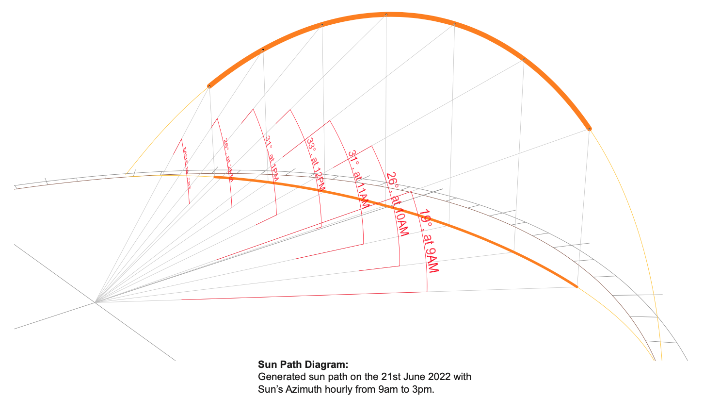
The sun does not occupy a fixed position in relation to a site. Its apparent path changes through the day and across the seasons, altering the angle, duration and intensity of direct sunlight that reaches a building. Sun path analysis helps translate this changing movement into a project-specific understanding of solar access.
Two relationships are central to the analysis. Solar altitude describes how high the sun is above the horizon, while solar azimuth describes its horizontal direction around the site. Together, these determine whether direct sunlight can reach a façade, window, balcony, courtyard or other part of the development at a selected time.
Solar access is also affected by building orientation, massing, setbacks, neighbouring development, topography and architectural elements such as eaves, screens and recessed glazing. A Sun Eye Diagram brings these factors into one spatial view so the relationship between sun position and built form can be interpreted more clearly.
Vertical position
The height of the sun above the horizon influences shadow length, façade exposure and the depth to which direct sunlight may penetrate.
Horizontal direction
The direction of the sun around the site determines which elevations and spaces are exposed at different times of day.
Built context
Existing and proposed buildings, terrain and architectural elements determine whether a direct solar path remains open or becomes obstructed.
A surface may receive sunlight at one time and be fully obstructed at another. Reliable analysis therefore depends on the project location, date, time, orientation and surrounding context being considered together rather than in isolation.
Seasonal Solar Response
The relationship between a building and the sun changes significantly through the year. In winter, the sun follows a lower path across the sky and produces longer shadows. In summer, it rises higher and can expose roofs, façades and outdoor spaces to more direct solar radiation.
Site orientation determines how these seasonal changes are experienced by different parts of a development. A northern façade may receive useful winter sun while still requiring carefully designed summer shading. Eastern and western elevations are exposed to lower-angle morning and afternoon sun, which can be more difficult to control through horizontal shading alone.
Sun Eye Diagrams allow these relationships to be reviewed at selected dates and times. This can help design teams test whether orientation, building form and surrounding obstructions support the intended solar outcome before those decisions become fixed in the design.
Winter
Lower sun angles create longer shadows and make surrounding height, setbacks and orientation more influential to direct solar access.
Summer
Higher sun paths can increase exposure to roofs, façades and open spaces, making external shading and façade response important.
Orientation
Each elevation responds differently to solar direction, surrounding obstruction and the time of day being assessed.
Design interpretation
A theoretically favourable orientation may perform differently once neighbouring buildings, terrain, proposed massing and local constraints are included. Spatially contextual solar analysis helps reveal the actual relationship rather than relying on orientation principles alone.
Spatial Context
Sun Eye analysis becomes more useful when a proposed building is assessed within an accurate representation of its surrounding context. Certified Energy uses Urbanfinity Spatial Data to help place project geometry within a georeferenced three-dimensional environment that may include neighbouring buildings, terrain and broader urban form.
This spatial foundation can reduce reliance on simplified or manually reconstructed context models. It allows the relationship between solar position, proposed massing and surrounding obstruction to be reviewed more clearly and consistently, particularly on complex urban sites where nearby development has a direct influence on solar access.
The analysis remains project-specific. Architectural information, site orientation, nominated dates and times and the purpose of the assessment are brought together with available spatial data to create diagrams that respond to the actual design question rather than producing a generic visualisation.
Georeferenced context
Spatial data helps align project and surrounding geometry with the geographic location used for the solar calculation.
Surrounding development
Nearby buildings and urban form can be represented where data is available, helping identify possible obstruction and exposure.
Terrain and site form
Available terrain information can help explain how slope, level changes and broader site form influence the solar relationship.
Certified Energy + Urbanfinity
Urbanfinity helps establish the three-dimensional setting around the project. Certified Energy applies the project geometry, solar position, nominated assessment conditions and architectural interpretation required to turn that context into a usable Sun Eye Diagram.
Architectural Response
Sun Eye Diagrams can be used as a design-testing tool rather than only as a final presentation graphic. By showing how direct sunlight relates to proposed building form, they allow architects and design teams to review orientation, massing, setbacks, openings and outdoor spaces while there is still an opportunity to refine the proposal.
The analysis can reveal whether a design intention is being achieved in the actual site context. A courtyard may appear well oriented in plan but remain obstructed during important winter periods. A façade may receive more low-angle afternoon sun than expected. A change in height, separation or building alignment may improve solar access to an apartment, terrace or shared outdoor area.
Because the solar relationship can be reviewed at nominated dates and times, alternative design options can be compared against the same conditions. This helps move discussions beyond general orientation principles and towards evidence that is specific to the project, location and surrounding built form.
Building form
Test how building height, depth, articulation, setbacks and separation influence direct solar access across the site.
Internal planning
Review the solar relationship of windows, balconies, living areas and other occupied parts of the proposal.
External areas
Investigate how proposed and surrounding buildings affect solar access to terraces, courtyards, plazas and communal spaces.
Design options
Compare different massing, orientation or setback options under consistent solar conditions.
Early design value
Reviewing solar access during concept and design development can make the findings actionable. The analysis can then inform architectural decisions rather than simply document the consequences of decisions that have already been made.
Façade Performance
A building façade responds differently to the sun depending on its orientation, geometry and surrounding context. Sun Eye Diagrams can help reveal when direct sunlight reaches a façade, which architectural elements provide protection and where exposure may remain difficult to control.
Horizontal eaves may provide effective protection from higher summer sun on suitably oriented façades, while lower-angle eastern and western sun may require deeper reveals, vertical fins, screens or a different arrangement of openings. The usefulness of any shading response depends on the actual solar angle and the position of the building within its site.
Sun Eye analysis does not replace detailed thermal or daylight modelling. It provides an earlier spatial understanding of exposure and obstruction that can help identify where further façade, glazing, comfort or internal daylight assessment may be valuable.
Fixed shading
Review whether fixed architectural elements align with the relevant sun angles and seasonal exposure.
Façade articulation
Explore how façade depth and vertical or angled elements influence direct exposure throughout the day.
Glazing response
Identify windows and glazed areas that may receive direct sun at relevant times and require further design review.
Passive response
Support design decisions that seek useful seasonal sunlight while limiting unwanted exposure and overheating risk.
The objective is usually to understand where direct sun is beneficial, where it may create unwanted exposure and how the architecture can respond appropriately to season, orientation and use.
Analysis Comparison
Sun Eye Diagrams and Shadow Diagrams both examine the relationship between buildings and sunlight, but they present that relationship from different perspectives. A Sun Eye Diagram focuses on whether direct sunlight can reach a selected building surface or space. A Shadow Diagram focuses on where the shadow cast by a building falls at a nominated date and time.
The two methods can be complementary. Shadow Diagrams are commonly used to communicate overshadowing across sites, neighbouring properties and outdoor spaces. Sun Eye Diagrams can add a more direct three-dimensional explanation of solar access to façades, windows, apartments, courtyards and other selected parts of a development.
Solar reach
Examine the relationship between the sun and selected parts of a building or site.
Cast shadow
Examine where the shadow created by existing or proposed buildings falls.
Practical distinction
Sun Eye analysis asks whether the sun can reach or “see” a selected surface. Shadow analysis asks where the building blocks sunlight and casts shadow.
One method should not automatically be treated as a substitute for the other. The appropriate output depends on the planning requirement, design question and evidence needed for the project. Some assessments may benefit from both methods being prepared and reviewed together.
Related Building Analysis
Sun Eye Diagrams establish the external solar relationship between the sun, the building and its surrounding context. They help show whether direct sunlight can reach a façade, window or outdoor space at a selected date and time. Daylight Modelling and Thermal Comfort Modelling investigate different layers of building performance.
Daylight Modelling examines how natural light enters and distributes through internal spaces. It may consider window size, room geometry, surface reflectance, surrounding obstruction and diffuse sky light as well as direct sun. A space can therefore receive useful daylight even when direct solar access is limited.
Thermal Comfort Modelling considers how solar gains interact with glazing, insulation, thermal mass, ventilation, internal loads and local climate conditions. Sun Eye analysis can identify where direct exposure occurs, but further modelling may be needed to understand whether that exposure supports winter comfort or contributes to overheating and discomfort.
External solar relationship
Show whether direct sunlight can reach selected building surfaces and spaces within the surrounding three-dimensional context.
Interior light conditions
Assesses the availability and distribution of natural light within rooms and occupied spaces.
Explore Daylight ModellingOccupant experience
Examines how environmental and building conditions influence the thermal experience of occupants.
Explore Thermal Comfort ModellingA layered assessment approach
Sun Eye analysis can provide an early spatial understanding of solar exposure and obstruction. Daylight or thermal modelling can then investigate how those external conditions translate into measurable internal light, heat gain and occupant comfort outcomes.
Project Applications
Sun Eye Diagrams can support a wide range of architectural, development and planning projects where direct solar access needs to be understood in three dimensions. Their value is strongest where building form, surrounding development or site geometry makes the solar relationship difficult to interpret through plans and conventional shadow drawings alone.
The scope of the analysis should respond to the project question. Some projects require early design testing, while others need clear visual evidence for planning documentation, design review or communication with consultants and approval authorities.
Residential
Commercial
Planning
Project suitability
The appropriate method depends on the scale of the development, the complexity of the surrounding context, the planning requirement and the decision the analysis needs to support. Certified Energy can review available project information and help determine whether Sun Eye Diagrams, Shadow Diagrams or a combination of both is the more suitable response.
Project Information
A Sun Eye analysis is prepared from project geometry, site information and the solar conditions relevant to the design or planning question. The quality of the output depends on the proposed building and surrounding context being represented at an appropriate level of accuracy.
Certified Energy can begin with the information currently available and identify whether additional survey, model or contextual data is required. Where suitable Urbanfinity Spatial Data is available, it may be used to strengthen the representation of neighbouring buildings, terrain and urban form.
Site information
Design information
Assessment brief
Analysis Process
Step 01
Confirm the project question, relevant locations, dates, times and intended use of the diagrams.
Step 02
Coordinate the proposed design with available survey, contextual building and terrain information.
Step 03
Position the sun using the project location and the nominated seasonal, date and time conditions.
Step 04
Produce selected views and explanatory material suited to the design, planning or coordination purpose.
Design Stage Timeline
Sun Eye Diagrams are most valuable during concept and schematic design, after the site context has been established but before the building form and façade response become fixed. They provide early solar design intelligence that can guide more detailed analysis as the project develops.
Site Context
Concept Design
Sun Eye Diagrams
Design Refinement
Detailed Analysis
Following the Sun Eye review, the project may progress to more specialised assessments such as Shadow Diagrams for planning documentation, Solar Access and Overshadowing Analysis for defined planning impacts, Daylight Modelling for internal daylight performance or Thermal Comfort Modelling for occupant comfort outcomes.
Project Outputs
Sun Eye deliverables should be prepared around the specific design or planning question being tested. The output may range from a focused set of three-dimensional solar views to a broader package comparing dates, times, design options or selected parts of a development.
The diagrams are intended to make complex solar relationships easier to interpret. They can be incorporated into architectural presentations, planning reports, design statements and consultant coordination packages, with the level of annotation and explanation matched to the project purpose.
Visual analysis
Project-specific views illustrating the sun, proposed development and surrounding spatial context at nominated dates and times.
Comparison
Comparative diagrams can help explain how a proposal or design revision changes solar access under consistent conditions.
Documentation
Views can be assembled with dates, times, locations and explanatory notes suitable for inclusion within a wider project package.
Interpretation
Supporting commentary can identify the relevant obstruction, exposure or architectural relationship shown by each view.
Design Team Coordination
Architects usually define the design question, project geometry and parts of the proposal requiring review. Surveyors and spatial datasets help establish the site and surrounding context. Planners identify the relevant controls or evidence needed for assessment. Certified Energy brings these inputs together within the solar analysis and prepares outputs that can be understood across the project team.
Early coordination is particularly valuable where the project involves complex massing, multiple design options, incomplete context information or a specific request from an approval authority. Confirming the required locations, dates, times and presentation format before modelling begins helps keep the analysis aligned with the intended decision.
Scope before output
A larger number of views does not automatically create better evidence. A focused scope can make the relevant solar relationship easier to communicate and reduce unnecessary modelling or documentation.
Choosing the Right Assessment
Sun Eye Diagrams provide an excellent understanding of how the sun relates to a proposed building, but they are not intended to answer every environmental or planning question. As projects become more detailed, additional specialist assessments may be required depending on the project's objectives and approval requirements.
If a project needs to demonstrate where shadows fall at nominated times and dates for a planning application, formal Shadow Diagrams are generally required. These assessments focus on shadow extent rather than the spatial relationship between the sun and the building.
Where planning controls require assessment of neighbouring properties, open space or windows, a Solar Access and Overshadowing Analysis may be necessary to evaluate compliance against the relevant planning criteria.
Understanding where sunlight reaches a building is different from predicting daylight levels inside occupied spaces. For quantitative daylight metrics, Daylight Modelling provides a far more detailed assessment.
Sun Eye Diagrams indicate solar exposure but do not predict indoor temperatures or occupant comfort. Projects investigating overheating, façade performance or occupant experience may require Thermal Comfort Modelling.
Sun Eye Diagrams help explain how the sun interacts with a proposed building in three dimensional space. They provide valuable design intelligence during the early stages of a project, helping architects and consultants understand solar opportunities before more detailed technical assessments are undertaken.
As the design progresses, they are often complemented by specialist studies that answer more specific questions relating to planning compliance, solar access, daylight performance or thermal comfort. Together, these assessments create a more complete understanding of building performance throughout the design process.
Future Building Response
As Australian buildings become more responsive to climate, comfort and energy performance, solar analysis is increasingly valuable as an early design input. Orientation, massing, façade depth and shading can shape how a building experiences heat, light and seasonal change long before detailed systems are selected.
Sun Eye Diagrams provide a clear spatial layer within this wider environmental design process. They help teams understand where solar access is available, where surrounding development limits it and where architectural decisions may improve the relationship between the building and its site.
The future value of this analysis lies not in producing more diagrams, but in connecting accurate spatial data with timely design decisions. When solar access is reviewed alongside daylight, thermal comfort, façade performance and planning context, the building can respond more coherently to its environment.
Earlier insight
Solar relationships can be reviewed during concept design, when changes to orientation, massing and setbacks remain practical.
Better context
Georeferenced surrounding buildings and terrain help move solar analysis beyond isolated project models.
Integrated performance
Findings can guide more detailed daylight, façade and thermal comfort investigations where required.
The broader direction
Sun Eye analysis provides one clear view of those relationships, helping design teams see how solar movement, site context and architectural form come together across time.
Frequently Asked Questions
A Sun Eye Diagram is a three-dimensional solar access view showing the position of the sun in relation to a building, site and surrounding context at a selected date and time. It can help demonstrate whether direct sunlight reaches particular façades, windows, apartments, balconies, courtyards or outdoor spaces.
A Sun Eye Diagram examines whether the sun can reach a selected building surface or space. A Shadow Diagram shows where the shadow cast by a building falls. The two methods may be used together, but they answer different design and planning questions.
Sun Eye Diagrams can be useful where building massing, surrounding development or site geometry makes solar access difficult to understand through conventional plans alone. Common applications include apartment developments, mixed-use projects, urban infill, communal open-space assessments, façade studies and planning submissions requiring clearer solar evidence.
Sun Eye Diagrams may support planning documentation where three-dimensional solar access evidence is relevant. The required format varies between projects and approval authorities, so the planning brief, relevant controls and any request for additional information should be reviewed before the scope is confirmed.
The analysis can be prepared for selected dates and times relevant to the project. These may be established by a planning control, design objective, consultant brief or request from an approval authority. Multiple conditions can be compared where seasonal or time-based changes need to be understood.
Useful inputs include the project address, survey, site boundaries, true north, architectural plans, elevations, sections, proposed levels and a coordinated 3D model where available. The required assessment dates, times, viewpoints and planning purpose should also be identified.
A coordinated 3D model can make the process more efficient, but it is not always essential. Certified Energy can review the available plans and project information to determine whether sufficient geometry can be established for the required analysis.
Urbanfinity Spatial Data can provide georeferenced contextual information such as surrounding buildings, terrain and broader urban form. Where suitable data is available, this helps place the proposed development within a more complete three-dimensional site context and can strengthen the interpretation of solar access and obstruction.
No. Sun Eye analysis examines the external relationship between direct sunlight and the building. Daylight Modelling investigates how natural light enters and distributes through interior spaces. A project may require one or both methods depending on the question being assessed.
Yes. Early analysis can help compare orientation, height, setbacks, separation, façade exposure and massing options before the design becomes fixed. This is often more valuable than using the diagrams only to document a completed proposal.
Related Knowledge
Sun Eye Diagrams sit within a wider group of architectural and environmental-response services. Each method examines a different relationship between the building, its site, surrounding development and internal performance.
Overshadowing Analysis
Understand where proposed or existing buildings cast shadow at nominated dates and times.
Explore Shadow DiagramsInterior Light Performance
Assess how natural light enters, distributes through and performs within occupied interior spaces.
Explore Daylight ModellingOccupant Experience
Examine how solar gains, building fabric, ventilation and climate conditions influence occupant comfort.
Explore Thermal ComfortSpatial Visibility
Understand where a proposed building or structure may be visible from across its surrounding context.
Explore Viewshed AnalysisBuilding Performance
Explore a detailed building-performance standard focused on comfort, airtightness and very low operational energy demand.
Explore Passive HouseProject Strategy
Coordinate environmental performance, compliance and modelling pathways across complex projects.
Explore ESD ConsultancySolar access, overshadowing, visibility, daylight and thermal comfort are related but distinct. Selecting the right method begins with identifying the decision the project team or approval authority needs the analysis to support.
Project Review
Send the available project plans, site information and any relevant planning request for an initial review. Certified Energy can help determine whether Sun Eye Diagrams, Shadow Diagrams or a coordinated solar access analysis is the most useful response.
Where suitable spatial data is available, Urbanfinity context can be incorporated to provide a clearer three-dimensional understanding of surrounding buildings, terrain and urban form.
Last reviewed: June 2026. This page is maintained by Certified Energy as part of its Sun Eye Diagrams Knowledge Hub.